Most QA teams in India understand GD&T in theory. The gap is in execution — specifically, knowing which instruments are capable of verifying which callouts, and at what production volume. This article closes that gap.
What GD&T Actually Controls (That Conventional Tolerancing Doesn't)
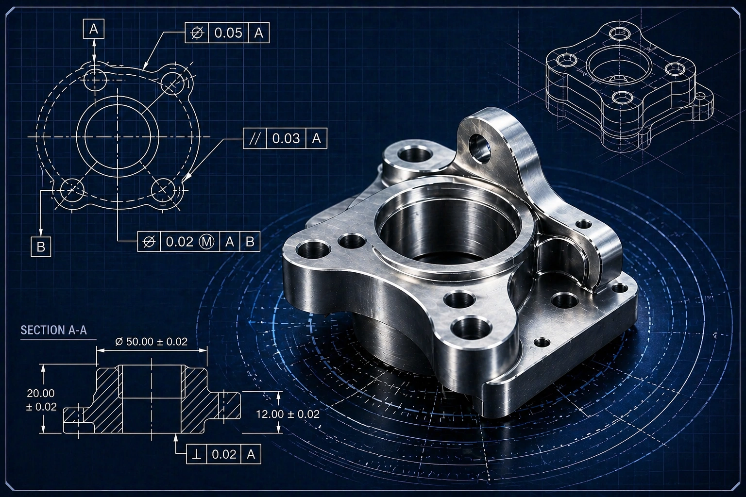
Conventional tolerancing gives you a size. GD&T gives you a geometric zone — a defined 3D space within which a feature must lie relative to a datum reference frame. The difference matters enormously in assembly and function.
Consider a bolt hole pattern. A ±0.1 mm positional tolerance on each hole independently doesn't tell you whether the pattern as a whole is correctly located. GD&T true position does — it controls the combined location relative to the datum surfaces that matter for assembly.
The 14 GD&T Characteristics — Grouped by Type
- Form controls (no datum required): Straightness, Flatness, Circularity, Cylindricity
- Orientation controls: Angularity, Perpendicularity, Parallelism
- Location controls: True Position, Concentricity, Symmetry
- Profile controls: Profile of a Line, Profile of a Surface
- Runout controls: Circular Runout, Total Runout
Each category has different measurement requirements. Form controls only need a single feature. Location controls need datum references. Runout controls need a rotational axis. Not every instrument handles all of them.
Which Optical Metrology Instruments Support Which GD&T Callouts
| GD&T Characteristic | Manual Profile Projector | CNC VPP / VMM | QMM (Quick Measuring Machine) |
|---|---|---|---|
| Straightness (2D) | Partial | Full | Full |
| Flatness | No | Full | Partial |
| Circularity / Roundness | Manual only | Full | Full |
| Angularity | Manual only | Full | Full |
| Perpendicularity | No | Full | Full |
| True Position | No | Full | Full |
| Profile of a Line | Overlay chart only | Full | Partial |
| Profile of a Surface | No | Full (with Z axis) | No |
| Circular Runout | No | With rotary fixture | With rotary stage |
| Concentricity | No | Full | Full |
Most Indian QA labs can verify diameter, length, and basic angle — but struggle to verify true position, perpendicularity, or profile callouts without a CMM. A CNC VMM fills this gap at a fraction of CMM cost for 2D/2.5D components, with significantly shorter measurement cycle time.
How Optical Instruments Measure GD&T in Practice
Datum Establishment
GD&T is meaningless without a datum reference frame. In optical measurement, datums are established by the measurement software — it fits a mathematical plane, axis, or point to measured features, then computes all subsequent callouts relative to that reference. A CNC VMM or QMM does this automatically within a part program. A manual projector cannot.
True Position Calculation
True position requires measuring the actual location of a feature (e.g., a hole centre) and comparing it to the theoretically exact location derived from the datum. The VMM software computes the deviation vector, converts it to a diametral zone, and compares it against the drawing tolerance. With Optomech's VPP-CNC 4030, this is done within a CNC part program — no manual calculation.
Profile of a Line
Profile of a line controls the form and location of a 2D cross-section. On a VMM, the instrument captures edge points along the profile at sub-pixel resolution, fits the resulting point cloud to a nominal CAD profile, and computes deviation across the full profile length. Aerospace and medical device manufacturers rely on this for complex contoured parts.
Need GD&T Verification on Your Components?
Our applications engineers can assess which Optomech instrument supports your specific GD&T callouts. No obligation.
The Real-World Limitation Most Engineers Miss
Optical metrology works in 2D and 2.5D. The fundamental limit of a video-based VMM is that it measures what it can see — and a camera sees a projected 2D image. For 3D surface callouts like profile of a surface across a complex contour, or for full cylindricity on a deep bore, a tactile CMM or CT scanner is more appropriate.
Where VMMs excel: components where GD&T callouts are 2D in nature — hole patterns, edge profiles, groove locations, shoulder angles, thread forms — and where measurement cycle time matters. A full automotive component inspection that would take 8–10 minutes on a CMM takes under 30 seconds on a CNC VMM.
What Most People Get Wrong About GD&T Measurement
The most common mistake is measuring features individually with a manual projector and calling it GD&T compliance. It isn't. GD&T requires verifying geometric relationships between features relative to a datum — something only a CNC instrument with multi-datum software can do reliably.
The second mistake is assuming all GD&T violations are dimensional errors. Often, true position failures come from fixturing inconsistency or datum surface contamination — not the part itself. A consistent measurement system reveals this; an inconsistent one masks it.
Practical Takeaway
If your component drawings carry GD&T callouts and your inspection equipment is a manual profile projector, you are likely passing non-conforming parts or rejecting conforming ones. The instrument doesn't have the capability to verify the specification.
A CNC VMM or VPP-CNC with GD&T software — such as Optomech's VMM CNC-HD — brings the measurement system in line with the drawing intent. For high-volume production, it also eliminates 80–90% of inspection cycle time compared to manual measurement.
If your drawings only have size and angle tolerances: a VPP-CNC is sufficient. If you have true position, perpendicularity, or profile callouts: you need a full CNC VMM with datum-based GD&T software. If you have runout or cylindricity on 3D contours: evaluate a CMM or CT scanner alongside VMM for complementary coverage.