When evaluating optical metrology instruments, most buyers look at accuracy specifications, software features, and price. Telecentric optics — the optical design of the imaging system — rarely comes up. It should be the first question asked.
Without telecentricity, your measurement results change based on how consistently the part sits on the fixture. That's not an instrument accuracy problem. It's a fundamental optical design problem — and it cannot be corrected by software or calibration.
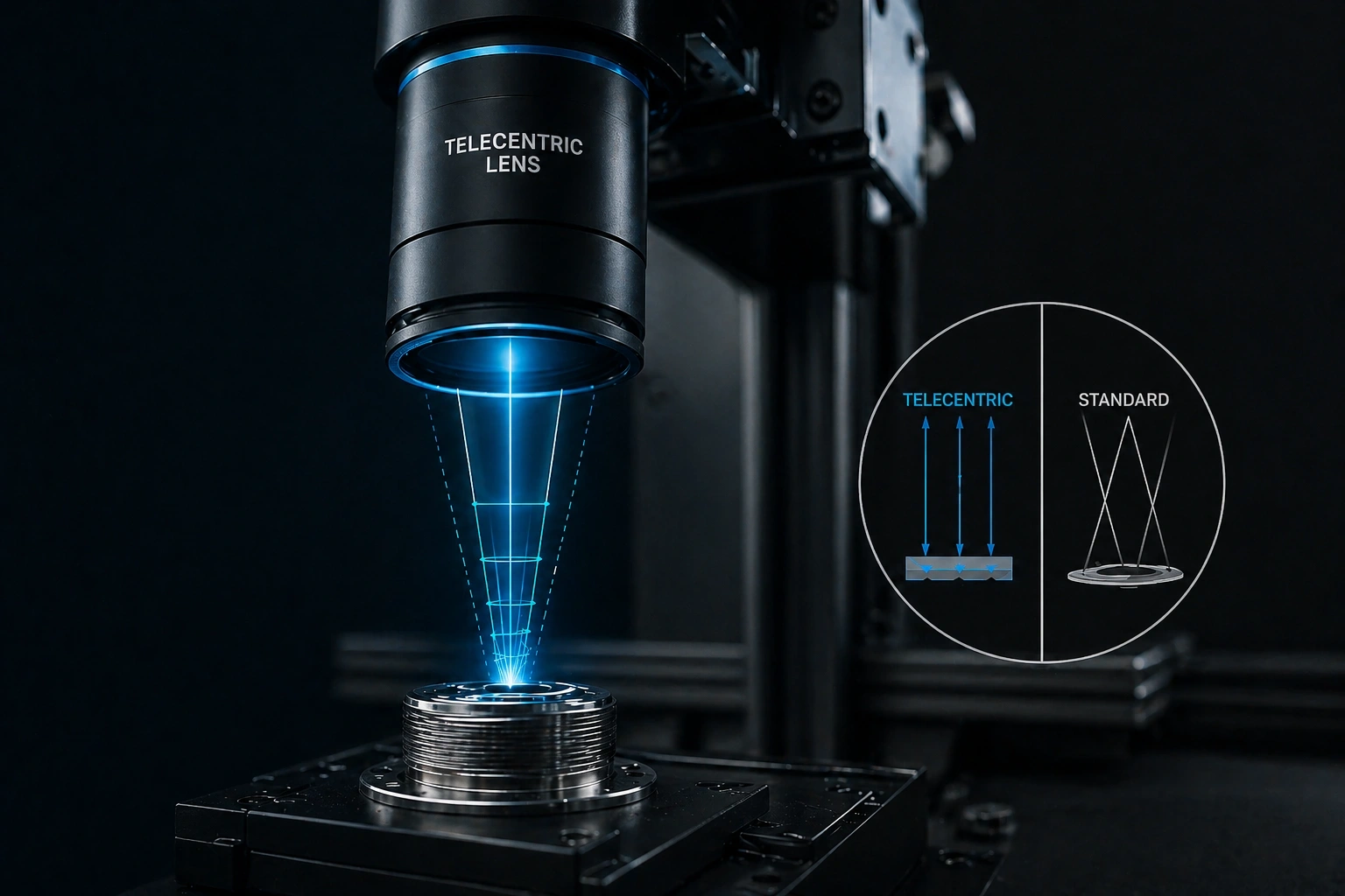
The Problem with Standard (Entocentric) Lenses
A standard camera lens has a single focal point. Objects closer to the lens appear larger; objects farther appear smaller. This is perspective — normal and expected in photography. But in dimensional measurement, this is an error.
Consider measuring the outer diameter of a turned shaft on a VMM with standard optics. If the shaft sits 0.3 mm higher on the fixture than during calibration (due to different coolant film, slight fixture wear, or part-to-part variation), the shaft now appears slightly larger to the camera — because it's closer to the lens. The measurement software faithfully reports a larger diameter. This is not the part changing. It's perspective distortion — and it's a systematic measurement error.
The error scales with magnification and the ratio of object height variation to working distance. At 2× magnification with 0.3 mm height variation at 100 mm working distance, the perspective error approaches 6 µm — a significant fraction of most production tolerances.
How Telecentric Lenses Solve This
A telecentric lens is designed so that the chief rays (the central axis ray of each cone of light from each image point) are parallel to the optical axis — not converging toward a single focal point. This means the image magnification is constant regardless of object distance, within the lens's depth of field.
An object 0.5 mm closer to a telecentric lens and 0.5 mm farther from it will produce the same image size — as long as it's within the specified depth of field. Part height variation due to fixturing inconsistency, part geometry variation, or thermal expansion does not affect the measurement result. The optics eliminate the perspective error source entirely.
Standard vs Telecentric: What Changes in Measurement
Conventional Optics
- Magnification varies with object distance
- 0.3 mm height change → up to 6 µm error at 2× mag
- Part seating variation directly affects measurement
- Cannot distinguish size change from position change
- Suitable for machine vision inspection, not precision metrology
- Lower cost, widely available
Metrology-Grade Optics
- Magnification constant across depth of field
- 0.3 mm height change → negligible measurement error
- Part seating variation does not distort measurements
- Errors from focus shift are symmetric (no bias)
- Required for reliable precision dimensional measurement
- Higher cost — essential for metrology-grade instruments
Quantifying the Error: When Does It Actually Matter?
The perspective error from non-telecentric optics follows a predictable relationship: E = M × ΔZ / WD, where M is magnification, ΔZ is height variation, and WD is working distance. For a typical 2× objective at 100 mm working distance:
| Part Height Variation (ΔZ) | Error with Standard Lens (2×, 100 mm WD) | Error with Telecentric Lens |
|---|---|---|
| 0.1 mm (minor fixture variability) | ~2 µm | <0.5 µm |
| 0.3 mm (typical shop floor fixture) | ~6 µm | <0.5 µm |
| 0.5 mm (worn fixture or variable parts) | ~10 µm | <1 µm |
| 1.0 mm (significant height variation) | ~20 µm | <2 µm |
For a part with a tolerance of ±20 µm, the perspective error from a standard lens with 0.3 mm fixture variability consumes 30% of the entire tolerance band — before any other error source is considered. For ±10 µm tolerances, this error alone exceeds the gauge R&R acceptance threshold.
Some budget VMM and optical inspection instruments use standard industrial camera lenses rather than purpose-designed telecentric metrology lenses — to reduce cost. This is not visible from photographs or specification sheets. Ask explicitly: "Is the imaging lens system telecentric for measurement?" and request the lens telecentricity specification. Reputable metrology manufacturers specify this as a core parameter.
All Optomech Instruments Use Telecentric Optics
VMM, QMM, VPP-CNC — every Optomech optical measurement instrument is designed with telecentric imaging as standard. See the difference with your own parts.
Bilateral Telecentricity — The Highest Standard
Standard telecentric lenses are object-side telecentric — meaning the rays are parallel on the object side, which eliminates measurement error from object height variation. This is sufficient for most metrology applications.
Bi-telecentric (doubly telecentric) lenses achieve telecentricity on both the object and image side. This eliminates any residual magnification change due to camera sensor positioning variation and provides the most stable relationship between object size and pixel count — important for the highest-precision applications (sub-µm measurement).
Optomech's VMM CNC-HD series uses bi-telecentric optics for precision measurement applications. The standard QMM and VPP-CNC series use object-side telecentric systems — providing the appropriate accuracy for their production inspection applications.
What Most People Get Wrong About Optical Metrology
The most common misconception: that software can compensate for non-telecentric optics. It cannot. Software calibration can correct for a fixed magnification value at a defined focal distance. But the error from non-telecentric optics is not fixed — it varies with part height, which varies part to part. You would need to know the exact height of every part to apply a correction, which defeats the purpose of automated measurement.
This is why telecentricity is not an "optional upgrade" in a metrology instrument — it's a prerequisite for reliable measurement. An instrument without it may produce impressive-looking numbers that are systematically wrong in a way that passes internal checks but fails when compared against a traceable CMM.
Practical Takeaway
When specifying or evaluating any optical measuring instrument — VMM, QMM, profile projector with digital readout, or machine vision system — ask whether the imaging lens is telecentric, and what the telecentricity specification is. If the specification isn't published or the answer is vague, treat it as a non-telecentric system.
For production inspection tolerances of ±20 µm or tighter, non-telecentric optics introduce unacceptable systematic error. For any application where measurements are used for quality system compliance, PPAP submission, or customer audit, telecentric optics are not optional.
You can check telecentricity simply on any optical instrument: measure a known reference ball or gauge block, then deliberately raise or lower it by 0.5 mm and measure again. With telecentric optics, the measured diameter should change by less than 1–2 µm. With non-telecentric optics, it will change by 5–15 µm depending on magnification. This test reveals the optical design immediately — no specification sheet required.