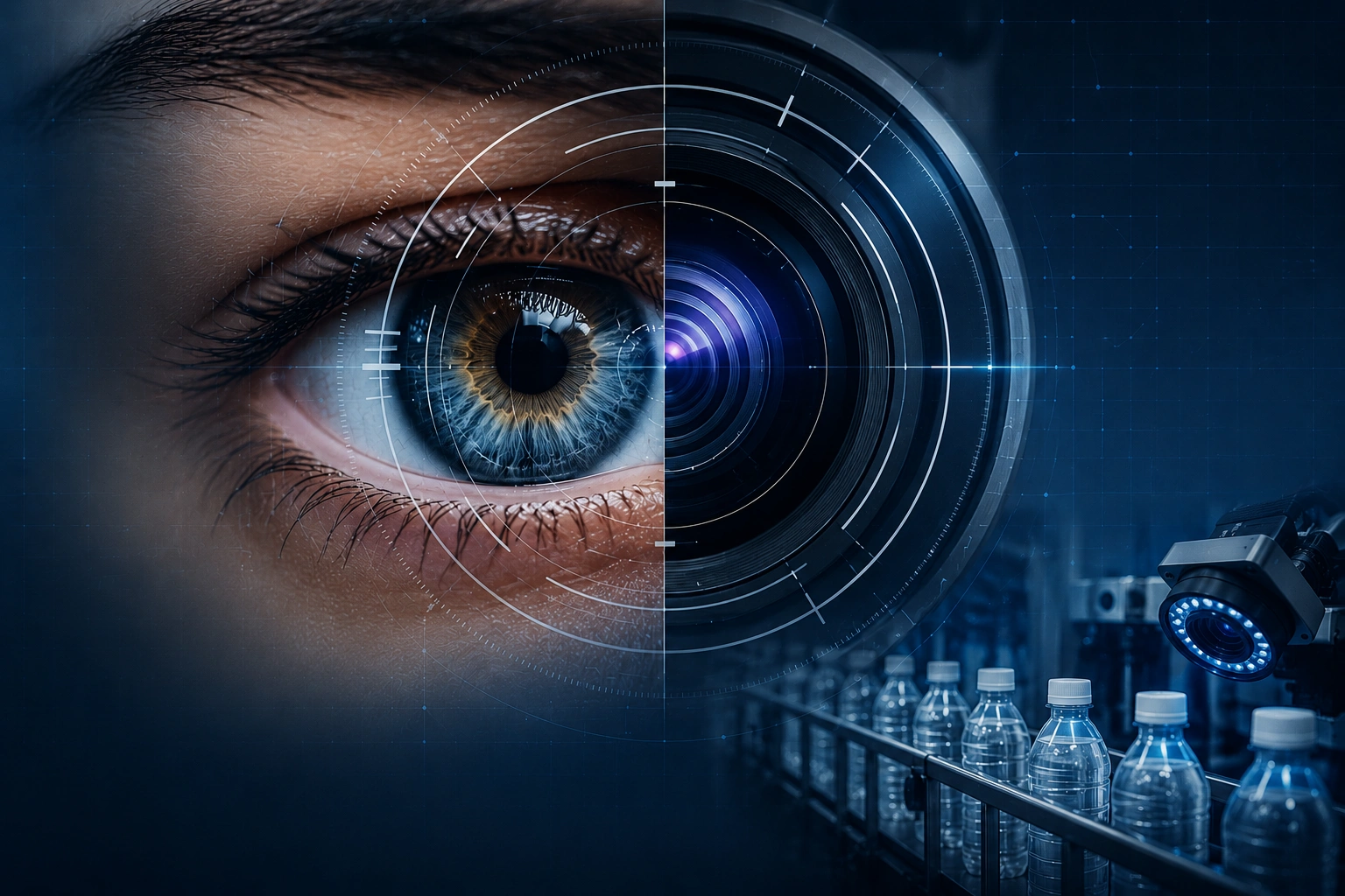
Machine vision lighting techniques are the most underrated part of any inspection system. Teams spend lakhs on cameras, lenses and software, then mount a random LED bar and wonder why the system rejects good parts and passes bad ones.
Here's the uncomfortable truth experienced integrators repeat constantly: a vision system can only analyse the contrast the lighting creates. If a defect doesn't visibly separate from the background in the captured frame, no resolution and no algorithm will recover it reliably. Lighting isn't an accessory — it's the foundation.
Why Lighting Is 80% of a Vision Solution
A camera records light, not objects. A defect only becomes detectable when lighting converts it into a difference in brightness, colour or shadow the sensor can capture. The job of machine vision lighting is to maximise the contrast between the feature you care about and everything you don't.
Get this right and the rest of the system becomes easy — simple thresholds reliably separate good from bad. Get it wrong and you're left fighting the image with software filters, chasing a moving target that drifts every time ambient light, part colour, or line speed changes. That's why the field rule of thumb is that lighting and optics together account for around 80% of whether a vision project succeeds.
You are not lighting the part — you are lighting the defect. Before choosing any light, define exactly what you need to detect, what it looks like physically (a height change, a colour change, a scratch, a missing item), and how that physical property can be turned into image contrast.
The Core Lighting Techniques — and What Each One Reveals
Most industrial inspection problems are solved by one of a handful of lighting geometries. Knowing what each does is the difference between a robust system and a fragile one.
1. Backlighting
The light sits behind the part; the camera sees a dark silhouette against a bright field. This produces the highest-contrast edges possible and is unbeatable for dimensional measurement, presence/absence, hole and gap checks, and outline verification.
- Best for: measuring outer profiles, checking fill level in bottles, counting, edge and shape gauging.
- Watch out: it shows shape only — it tells you nothing about surface markings or printed text.
2. Diffuse Dome (Cloudy-Day) Lighting
A hemispherical dome bathes the part in even light from every angle, eliminating glare and hotspots. This is the go-to for shiny, curved or textured surfaces — exactly the bottle caps, foils and metallised labels common on packaging lines.
- Best for: reflective caps, induction seals, curved containers, reading print on glossy surfaces.
- Watch out: it deliberately suppresses shadow, so it's poor at revealing fine surface texture or embossing.
3. Dark-Field (Low-Angle) Lighting
Light strikes the surface at a shallow grazing angle. A flat, clean surface reflects it away from the camera and appears dark — but any scratch, edge, engraving or raised mark scatters light back and lights up brightly.
- Best for: scratches, cracks, embossed/engraved codes, surface contamination, edge chips.
- Watch out: very sensitive to working distance and part height variation; needs stable part presentation.
4. Bright-Field & Coaxial Lighting
Light comes from the same direction as the camera (coaxial uses a beam-splitter to make it perfectly on-axis). Flat reflective surfaces appear bright; anything that deflects the light — a dent, a pit, a non-flat mark — appears dark.
- Best for: flat specular surfaces, mirror-finish parts, reading marks on metal, detecting dents on flat foils.
- Watch out: on non-flat or matte parts it can wash out detail; geometry must be controlled.
Have a Defect Your Current System Keeps Missing?
Send us a sample. Optomech's vision team runs lighting trials on your actual parts and shows you, with real images, which illumination makes the defect detectable.
Quick Reference: Which Light for Which Defect
| Inspection Task | Recommended Lighting | Why |
|---|---|---|
| Dimension / outline / fill level | Backlight | Maximum edge contrast via silhouette |
| Cap, foil or curved-surface defects | Diffuse dome | Removes glare on reflective curves |
| Scratches, cracks, embossing | Dark-field (low angle) | Surface relief scatters light |
| Marks/dents on flat shiny metal | Coaxial / bright-field | On-axis light exposes non-flat features |
| Colour-coded print verification | Colour light + mono camera | Colour choice maximises contrast |
Colour: The Lever Most People Ignore
Light colour is a free contrast tool. On the colour wheel, opposite colours suppress each other and similar colours brighten each other. Use blue light and a red mark goes dark; use red light and a red background disappears.
This is why a monochrome camera paired with the right colour light often beats an expensive colour camera for defect detection — it isolates exactly the contrast you need and ignores the rest. For date/batch code verification on coloured packaging, choosing the light colour is frequently the entire solution.
What Most People Get Wrong About Vision Lighting
The single most common mistake is treating lighting as an afterthought — picking the camera and software first, bolting on whatever light is in the drawer, and then trying to rescue a weak image in software. Software cannot create contrast that was never captured. The correct order is lighting first, then optics, then camera, then software.
The second mistake is ignoring ambient light. Sunlight through a shed window or overhead factory lights change through the day and overwhelm a weak inspection light, so a system that worked at commissioning fails by afternoon. Robust systems shroud the inspection station and often use high-intensity strobed lighting that dominates ambient and freezes motion on fast lines.
The third is buying on camera specs alone. A 12 MP camera under bad lighting detects less than a 2 MP camera under correct lighting. Resolution cannot substitute for contrast.
If a vision vendor quotes a system from a brochure without asking to see your actual parts and run a lighting trial, be cautious. No competent integrator specifies lighting blind. The defect, the surface, the part colour and the line speed all decide the lighting — and the lighting decides whether the system works. Always insist on a sample trial with images of your defects.
Practical Takeaway
Before you compare cameras or software, answer three questions: What exactly must be detected? What is the physical nature of that feature — shape, surface, or colour? And which lighting geometry turns it into the strongest possible contrast? Get those right and inspection becomes reliable and low-maintenance.
This is exactly how Optomech engineers every system — ISIVS, bottle, cap and label inspection lines included. Each is built around a lighting design proven on the customer's own parts, not a generic configuration. That's why they hold up to real production speeds and 100% inline duty.
Take your part to a dark room and try three things: hold a torch behind it (backlight), shine it straight on (bright-field), then graze it across the surface at a low angle (dark-field). Watch which one makes your defect jump out. That five-minute experiment usually tells you the lighting geometry your production system needs.