The Short Answer
Choose a VMM when most of your critical features are in one plane (XY) and visible from above, when parts are small, thin, soft, flat or reflective, and when you need to measure many parts quickly. Choose a CMM when features are truly 3D, on several faces, deep inside bores, or need form and Z-height accuracy that a camera can't achieve. Most precision shops end up with both and route each part to the machine that suits it.
How Each Machine Measures
CMM: contact probing in three axes
A coordinate measuring machine moves a probe (touch-trigger or scanning) until it contacts the surface, then records the XYZ position. Software fits circles, planes and cylinders through those points and evaluates GD&T. Because it works by touch, it reaches anywhere the stylus can get to: several faces, internal bores and freeform surfaces. Each point takes time, though, and the probe has to physically touch every feature.
VMM: calibrated imaging and edge detection
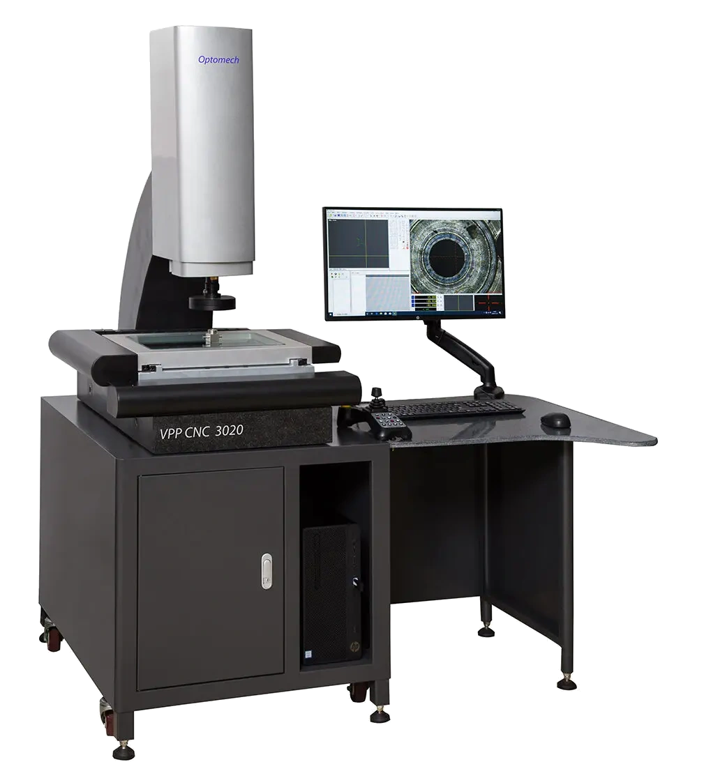
A vision measuring machine moves a calibrated camera and optics over the part on a precision XY stage with linear scales. Software detects edges in the image and turns pixel positions plus stage position into coordinates. One image can contain dozens of edges, and nothing touches the part. Motorised Z with autofocus adds height information, and some models accept an optional touch probe for features the camera can't see. Read more on the Optomech VMM range.
Side-by-Side Comparison
| Factor | VMM (vision measuring machine) | CMM (coordinate measuring machine) |
|---|---|---|
| Measuring principle | Non-contact: camera, optics and edge detection | Contact: tactile or scanning probe (optical sensors available on some) |
| Strongest at | 2D/2.5D features: hole patterns, profiles, radii, slots, small features | True 3D: multiple faces, deep bores, freeform surfaces, form |
| Part types | Small, flat, thin, soft, delicate, reflective, moulded, stamped, PCB and film | Prismatic and machined parts, castings, larger 3D parts |
| Features the other can't easily do | Very small radii and edges that are smaller than a probe tip; parts that deflect under probe force | Features hidden from a top view; undercuts and internal geometry |
| Throughput on many 2D features | High: many edges per image, CNC routines | Lower: one point per touch, probe changes |
| Fixturing | Often simple: parts laid flat in the field of view | Often more involved for multi-face access |
| Operator skill | Lower for routine CNC programs; learn-mode programming is common | Higher for programming and probe strategy |
| Environment | Stable temperature still needed for full accuracy; usually bench-top | Usually a temperature-controlled room; larger footprint |
How to Read an Accuracy Specification
VMM and CMM accuracy is usually written as a length-dependent maximum permissible error, in the form (A + L/K) µm, where L is the measured length in millimetres. Optomech publishes these figures for its VMM range:
| Model | Published spec | At L = 50 mm | At L = 100 mm | At L = 300 mm |
|---|---|---|---|---|
| VMM CNC | (2.5 + L/250) µm | 2.7 µm | 2.9 µm | 3.7 µm |
| VMM MAZ | (2.7 + L/250) µm | 2.9 µm | 3.1 µm | 3.9 µm |
Three things to check when comparing quotations:
- Which axes it applies to. VMM specifications usually describe XY. Z accuracy, which depends on autofocus, is typically larger and often specified separately.
- How it was tested. The ISO 10360 series defines acceptance tests. ISO 10360-2 covers CMMs measuring size, and ISO 10360-7 covers CMMs with imaging probing systems, which is the category VMMs fall into. Ask which test, which artefact and which conditions apply.
- Resolution is not accuracy. A 0.1 µm scale resolution doesn't mean 0.1 µm accuracy. Read measurement uncertainty explained for the difference.
Then compare against your tolerance. A common rule of thumb is that the measuring system should use only a small fraction of the tolerance band. A gauge R&R study on your own parts is the best proof.
When a VMM Wins
- Plastic and moulded parts that deflect under probe force. See optical metrology for moulded parts.
- Stampings, gaskets, shims, PCBs and films, which are thin, flat and full of 2D features. See stamped metal parts.
- Very small radii, chamfers and edges where a probe tip is too large to resolve the feature.
- Batch and first-article inspection where the CMM queue is the bottleneck. See batch inspection vs the CMM queue and first article inspection on a VMM.
- Reverse engineering of profiles with DXF export and CAD comparison.
In our aerospace case study from Hyderabad, the components had small radii that were not practical to measure on a CMM. A CNC VMM measured them without contact and greatly reduced inspection time. The case study page has the published details.
When a CMM Wins
- Features on several faces, measured in one setup against one datum system.
- Deep bores, internal grooves, undercuts and other features a top-down camera can't see.
- Freeform surfaces and 3D form: profile of a surface, flatness over large areas, cylindricity.
- Large castings and machined housings beyond the travel of a bench-top VMM.
- Tight Z-height tolerances, where tactile probing usually outperforms autofocus.
Cost of Ownership, Not Just Price
Compare more than the machine price: the environment it needs (room, air, foundation), operator training, programming time per new part, fixtures, calibration, software licences, and throughput, which tells you how many machines and operators you really need. Optomech VMM price bands are on our VMM price guide for India. Calibration should be traceable. See NABL traceability explained.
Using Both: The Hybrid Lab
Many quality labs route parts by feature type. 2D-dominant parts and high-volume batches go to a VMM or a Quick Measuring Machine (QMM). True 3D parts and the occasional full-layout inspection go to the CMM. This frees CMM time for the work only a CMM can do. If you are deciding between optical options, compare profile projector vs VMM and QMM vs CMM.
Optomech VMM Range at a Glance
| Series | Axes | Published spec highlights | Best for |
|---|---|---|---|
| VMM ME | Manual XY | 0.5 µm scale resolution; four stage sizes | Toolrooms and labs moving up from a profile projector |
| VMM MAZ | Motorised Z with autofocus | (2.7 + L/250) µm; touch probe optional | Mixed parts with height features |
| VMM CNC | 3-axis CNC servo | (2.5 + L/250) µm; 0.1 µm scales; learn-mode; SPC | Production batches, FAI, PPAP |
| VMM CNC HD | CNC with motorised zoom | Stage up to 600 × 500 mm | Larger parts, multiple magnifications |
Specifications as published on the Optomech VMM product pages. Confirm the configuration with our team for your application.